Introduction of Volkswagen's 3rd Generation EA888 Engine Water Pump
Published:2021-07-15
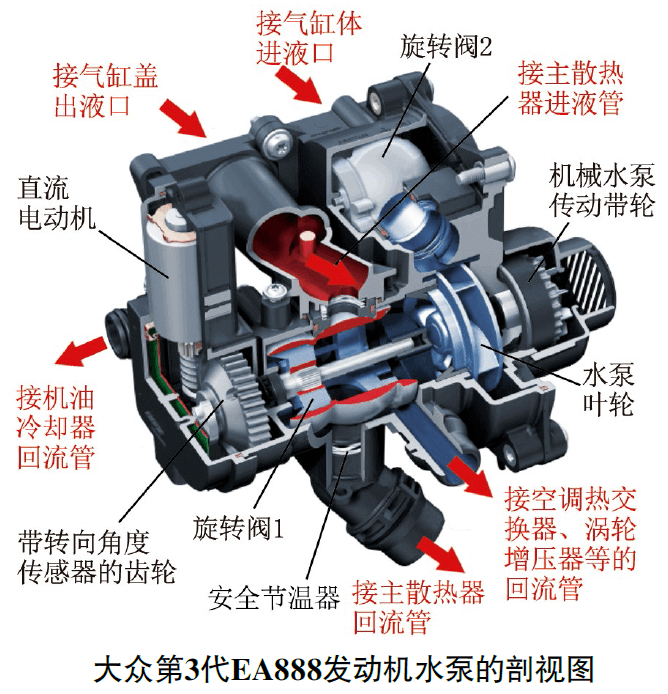
The water pump with temperature control actuator (N493) is one of the two core components of Volkswagen's third-generation EA888 engine's innovative thermal management system (ITM) (the other core component is the cylinder head integrated with the exhaust manifold). The water pump is mainly composed of mechanical water pump, N493 and related pipelines, among which N493 is composed of 2 rotary valves, DC motor, steering angle sensor and safety thermostat (expansion type).
 |  |
The mechanical water pump is driven by the balance shaft through the transmission belt. As long as the engine works, the mechanical water pump starts to run. The DC motor directly drives the rotary valve 1. The rotary valve 1 is responsible for controlling the flow of coolant between the oil cooler, the cylinder head and the main radiator. The rotation angle of the rotary valve 1 is monitored by the steering angle sensor. The rotary valve 2 is connected to the rotary valve 1 through a pin gear linkage mechanism, and will be linked and disconnected from the rotary valve 1 at a specific angle position. The rotary valve 2 is responsible for controlling the opening of the coolant pipe flowing into the cylinder block.

When the rotary valve 1 is at the 145° position, the rotary valve 1 and the rotary valve 2 start to link, slowly open the coolant pipe flowing into the cylinder block, and the coolant begins to flow to the cylinder block. As the rotary valve 2 rotates, the coolant flow rate increases. When the rotary valve 1 is at 85°, the rotary valve 2 reaches the maximum rotation angle. At this time, the rotary valve 2 is separated from the rotary valve 1, and the coolant pipeline to the cylinder block is completely turn on.
The engine control unit controls the operation of the DC motor according to various characteristic curves stored in it, and rotates the rotary valve 1 to a corresponding angle to open and close each coolant pipe, thereby quickly warming up the engine and keeping the engine coolant temperature at 86℃~107℃. N493 is divided into 4 working modes: warm-up, main radiator temperature adjustment, continuous operation after turning off the engine, and emergency heat dissipation. The warm-up mode is divided into static preheating, low-flow heat dissipation and turning on the oil cooler to preheat, etc. 3 stages. The specific working process is as follows.

(1) Static preheating. In order to quickly warm up the engine, turn the rotary valve 1 to the 160° position to close the oil cooler and the main radiator return pipe; the rotary valve 2 closes the coolant pipe flowing to the cylinder block; the air conditioner coolant shut-off valve (N422) is temporarily closed; The coolant continuous pump (V51) is not energized. At this time, the coolant does not circulate in the cylinder, and the stagnant coolant is heated to a maximum of 90°C according to the engine load and speed.
(2) Small flow heat dissipation. When the coolant in the cylinder block is not flowing, in order to prevent the cylinder head (integrated with the exhaust manifold) and the turbocharger from overheating, the rotary valve 1 is turned to the position of about 145°. From this position, the pin gear linkage mechanism Start to drive the rotary valve 2 to move, and the rotary valve 2 starts to open. At this time, a small amount of coolant will flow into the cylinder block, flow through the cylinder head and turbocharger, and then flow back to the water pump.
(3) Turn on the oil cooler to preheat. Since the rotary valve 1 reaches the position of 120°, the oil cooler return line begins to open. At the same time, the rotary valve 2 has continued to open, and the flow of coolant flowing into the cylinder block is increasing. Through this targeted switching on of the oil cooler, the engine oil can be additionally heated.

(4) Temperature adjustment of the main radiator. The innovative thermal management system seamlessly transitions from the warm-up mode to the main radiator temperature regulation mode. The adjustment of the rotary valve 1 and the rotary valve 2 is dynamic and depends on the engine speed and load. When the engine speed and load are very small, the coolant temperature will be adjusted to 107°C to minimize engine friction; as the engine speed and load increase, the coolant temperature will be lowered to a minimum of 85°C. During this process, the rotary valve 1 rotates at the position of 0°~85° according to the cooling needs. When the rotary valve 1 is at the 0° position, the main radiator return pipe is fully opened.
(5) Continue running after turning off the engine. In order to prevent the coolant at the cylinder head and turbocharger from boiling after the engine is turned off, and to avoid unnecessary cooling of the engine, the engine control unit will activate the continuous function according to the characteristic curve. This function can work for up to 15 minutes after the engine is turned off. For this reason, the rotary valve 1 is in the "continuous position" (160°~255° position). When the rotary valve 1 is at the position of 255°, the main radiator return pipe is fully opened, and the rotary valve 2 closes the cooling flow into the cylinder block. Liquid pipeline. In addition, the continuous coolant pump (V51) and the air-conditioning coolant shut-off valve (N422) are also activated, and the coolant is divided into 2 ways: one way flows through the cylinder head to the coolant continuous pump (V51), and the other way flows through the cylinder head to the coolant continuous pump (V51). The turbocharger flows to the rotary valve 1, and then flows back to the coolant continuous pump (V51) through the main radiator. In the continuous operation mode, the coolant in the cylinder block does not flow, which can significantly reduce the continuous operation duration without generating a large amount of heat energy loss.
(6) Emergency heat dissipation. If N493 fails, when the coolant temperature in the water pump reaches 113°C, the safety thermostat opens the bypass valve to the main radiator to ensure that the vehicle can still drive in emergency. N493 wire connector terminal 1 is the steering angle sensor ground terminal, terminal 2 is the steering angle sensor signal terminal, terminal 3 is the steering angle sensor 5V reference power terminal, terminal 4 is the negative pole of the DC motor, and terminal 5 is the positive pole of the DC motor.
- Distribution in Water Heater Mattresses: Why BLDC Pumps Ensure Uniform Heating
- How BLDC Pumps Ensure Precise Flow in Water Dispensers
- Why BLDC Pumps Are Essential for Smart Toilets
- The Critical Role of Automotive Electronic Water Pumps in New Energy Vehicle Battery Thermal Management
- Noise Control Technology for Smart Toilet Water Pumps: Enhancing Quiet Operation in Modern Bathrooms
- Unveiling the Working Principle of Automotive Electronic Water Valves
- Comparative Analysis of Liquid-Cooled Pumps vs. Air-Cooled Systems for EV Charging Stations
- Technical Application of Brushless DC Motors in Energy Storage Circulation Pumps
- Water Heater Pump: Efficiency Upgrade for Low-Voltage Systems
- How Dishwasher Water Pumps Enhance Cleaning Coverage Through Stable Operation?
