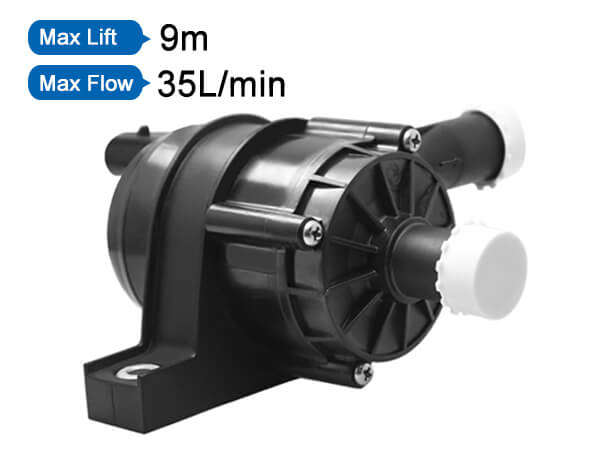
As an important part of the heating, hot water and central air-conditioning water system, how big is the right choice?
If the pump head selected in the design is too large, the surplus head will cause the exchange flow to increase, and the increase in flow will increase the noise of the pump. In addition, it will easily cause the motor load and current to increase, causing problems such as motor burn-in. If the selection is too small, it will lead to insufficient condensate/hot water at the end and affect the effect. Today, the editor conducts a detailed analysis of the pump selection calculation, allowing you to fully learn the pump selection in ten minutes.

The selection and calculation of the pump can be directly estimated by the calculation formula. A more detailed estimation and a more comprehensive consideration are accurate calculations. Selection calculation generally includes water pump flow calculation, simple estimation method of water pump head, practical estimation method of air-conditioning water pump head, etc. The specific selection algorithm is as follows:
1. Determination of the flow rate of the water pump
Flow rate is one of the important performance data of the water selection pump, and it is directly related to the production capacity and conveying capacity of the entire device. In the process design of the design institute, the normal, minimum and maximum flow rates of the pump are usually calculated. When selecting the pump, take the maximum flow rate as the basis and take into account the normal flow rate. When there is no maximum flow rate, usually 1.1 times the normal flow rate can be taken as the maximum flow rate.
Pump water flow: Generally select the water pump flow according to the value provided in the product sample (for example, the flow can be 1.1 to 1.2 times the rated flow of the air source unit (1.1 for a single unit, and 1.2 for two units in parallel) or calculate according to the following formula:
Q=1.163L*ΔT
----Q is the cooling capacity of the air source host
----L is the system cooling water flow
----ΔT is the system temperature difference
L(m3/h)= Q(kW)/(4.5-5)℃x1.163X(1.1-1.2)
2. Calculation of pipe diameter of water system
In the air conditioning system, all water pipe diameters are generally calculated according to the following formula:
D(m)=√L(m /h) /0.785x3600xV(m/s)
L----the water flow rate of the pipe section required (calculated in the first step)
V----The allowable water flow rate of the required pipe section
3. Determining the head of the water pump
The composition of the pump lift:
Hmax=△P1+△P2
----△P1 is the resistance along the pipeline.
----△P2 is the local resistance of the pipeline.
(1) Pressure loss along the system
The pressure loss along the way refers to the continuous and consistent pressure loss in the pipeline. Generally, the most unfavorable loop in the pipeline should be found. The branch pipeline loop with the farthest and most resistance in the pipeline network system is the pipeline network system. The most unfavorable loop.
△P1=Length of the most unfavorable pipeline*Specific friction
Generally, it is estimated that the loss along the way per 100 meters of pipe length can be roughly 5mH2O
(2) Partial resistance of the system
Partial pressure loss refers to the non-continuous pressure loss caused by special components in the pipeline system that change the direction of water flow or make local water flow channels narrow (such as reduced diameter, three-way, valve, joint, filter, etc.) , The local resistance is mainly composed of the following.
1. The water resistance of the air source unit: generally 6-8mH2O;
2. The water resistance of the surface cooler or evaporator of the terminal equipment (air handling unit, fan coil, etc.): generally 5-7mH2O;
3. The resistance of the backwater filter is generally 3-5mH2O;
4. Valve (check valve) water resistance: generally one is 3mH2O;
5. The local resistance loss of the water pipe tee and joint of the refrigeration system: generally 3-4mH2O;
In summary, according to the calculated total resistance, a safety factor of 10% is used to obtain the head of the pump.
Note: The calculation of the head should be based on the specific conditions of the relevant system, and the experience value should not be copied at will!
4. Determination of pump model, number and reserve rate
According to the two main performance parameters of the pump flow and head calculated above, the specific model is determined on the type spectrum or series characteristic curve. The operation is as follows:
curve
Using the pump characteristic curve, find the required flow value on the abscissa, and find the required head value on the ordinate, draw a vertical or horizontal line from the two values upwards and to the right respectively, and the intersection of the two lines just falls on the characteristic curve, then This pump is to be selected.
Under normal circumstances, customers can submit their "basic conditions for pump selection" to the corresponding pump manufacturer, who will give the pump model.
In household systems, generally only one pump is used for normal operation, because a large pump is equivalent to two small pumps working in parallel (referring to the same head and flow), and the efficiency of the large pump is higher than that of the small pump, so from the perspective of energy saving It is better to choose one large pump instead of two small pumps, but in the following situations, you can consider two pumps to cooperate in parallel:
1. The flow is very large, and one pump cannot reach the required flow;
2. For large pumps that require a 50% standby rate, two smaller pumps can be used, one for use and one for backup.
pump head formula,pump head vs flow rate,suction head of pump,pump head meaning,types of pump head,head range of pump means,shut off pressure of pump,how to increase pump head height
Address:No.30, Dapu lndustrial Street, Changping, Dongguan, Guangdong, China
Tel: +86-186 7628 8117